
Study on uplift load test of large-diameter steel pipe piles
1.0 Introduction
As an unceasing expansion of construction scale of infrastructure, the uplift pile has been widely used in high-rise buildings, cross-sea bridges, drilling platforms, large basements, and other infrastructure projects. Therefore, it is essential to study the bearing capacity behaviour of uplift piles in depth. Also, for the convenience of design, it is also essential to obtain the ultimate bearing capacity. Currently, the static load test is the most direct and reliable method to determine the ultimate bearing capacity of the pile foundation.
However, due to the limitations of many factors, such as considerable construction difficulty, high construction cost, and long test duration, many test piles start to stop loading before they break. Under this case, it cannot calculate the ultimate bearing capacity directly. At this time, other methods are required to determine their ultimate bearing capacity.
Steel pipe piles with a diameter of 1.6m are used for the foundation of the approach bridge in the sea area of Ningbo. Steel pipe piles in this project are made of Q345C steel. The length of these uplift piles is 89.6m, and the wall thickness of the pipe pile in the range of 45m below the top of the collection is 22mm, and the wall thickness for the rest part is 20mm.
There are four electronic displacement meters installed in the four corners of test piles to monitor the displacement on the top of the pile, s. Also, strainometer is arranged along the inside of the pile to measure the strain at the different sections. In the test, the fast load-keeping method was adopted, equivalent gradation loading. The loading and keeping the time of each level of the load was 1h, and the unloading and loading time of each level is 15min. During the loading process, the measurement will be conducted at 5, 10, 15, 30 and 60 min. During the uploading process, the measurement will be conducted at 5, 10 and 15min.
2.1 Analysis of Q-S curve and S-lgt curve of the test pile
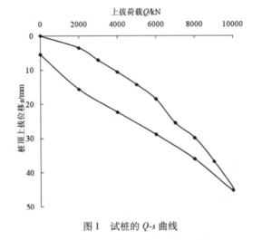
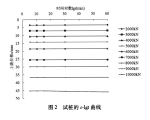
Figure 1, Q-S curve, illustrates the relationship between pulling force at the top of piles and pulling displacement at the top of piles during loading and unloading. Figure 2, S-lgt curve, illustrates the relationship between the displacement of the pile top and the log of action time.
The following conclusions can be drawn from these two figures:
With the increase of pile top lifting load, the displacement of pile top lifting increases. In the loading process, the load-displacement curve changes gently, and there is no obvious turning point. At the same time, the relationship between the displacement of the pile top and the log of action time presents as a horizontal line. These two curves show that the soil around the pile is in the elastic deformation phase, and the tensile bearing capacity of steel pipe pile is not fully exerted. For the ultimate bearing capacity of these steel pipe piles is greater than 10000kN.
After all the test piles are unloaded, the spring back displacement at the top of piles is 39.79mm, and the residual uplift amount is 5.46mm. The spring back rate is 87.93%, which indicates that most of the spring back is the tensile deformation of steel pipe pile, except for a small amount of spring back at the pile end.
2.2 Analysis of axial force distribution curve of the test pile
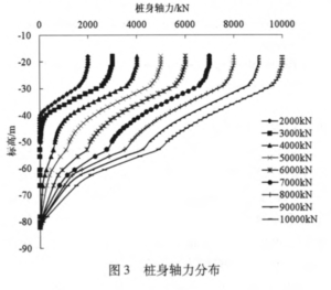
Based on the strain at the measured section, the axial force of the test pile is calculated by the formula, M= εEA (ε is the strain at the section, E is the elastic modulus of the pile, and A is the sectional area). The distribution curve of the axial force of the pile shaft along the depth is shown in Figure 3. The following conclusions are drawn from this figure:
The axial force of the test pile gradually decreases along with the depth and has different declining rates in different soil layers. It shows a nonlinear distribution and reflects the characteristics of friction pile.
The zero points of the first axial force appear at elevation -41m under the first level of load (2000kN) of the test pile. The axial force transferred to the pile top is zero when it is under the third level of load (4000kN). It can be seen; when the pulling load on the pile top is relatively small, the axial force gradually becomes to zero along with the pile depth. The pile below zero does not play a role. At this time, there is no pulling displacement on the pile top, and the pulling displacement on the pile top is caused by the tensile deformation of the pile body.
During the process of loading, the axial force at the pile tip is always zero, which conforms to the principle that the bearing capacity of the pulled pile is entirely borne by the lateral friction resistance.
Under various loads, the slope of the axial force distribution curve on the pile body remains basically unchanged. It indicates that the lateral friction resistance on the pile body has been fully exerted.
2.3 Analysis of the distribution curve of unit lateral friction resistance of test pile
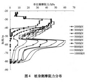
Test pile unit lateral friction resistance is calculated by the difference between two adjacent sections of pile shaft force through the formula q12=ᅀN/πDι (ᅀN is the difference of axial force between two sections, D represents the distance between sections, ι is pile diameter). The distribution curves of resistance along the depth are shown in Figure 4. The following conclusions can be drawn from Figure 4:
Pile lateral friction increases as the increase of pile roof uplift load. Under the action of uplift load on the top of piles at each level, the lateral friction resistance of pile body in a certain depth is basically identical with the load. It also indicates that the lateral friction resistance of piles in this depth range has been fully exerted. Below this range, pile lateral friction resistance increases with the increase of uplift load. It indicates that pile lateral friction resistance at the lower part of the pile body is not fully exerted.
Under the action of the third level load (4000kN), lateral friction resistance appears at the bottom t of the test pile and increases with the increase of load. This indicates that the lateral friction resistance at the bottom of the test pile lags behind that of the upper part and gradually increases in the later phase of loading.
3.0 Conclusion
The load-displacement curve changes gently without turning point. The uplift load did not reach its ultimate load, and the pile and soil are all in the elastic deformation stage.
The uplift load is transferred downward through the axial force of the pile, and through the lateral friction, it is transferred to the soil, forming the pile-soil interaction. The axial force of pile has different decreasing rates in different soil layers and presents nonlinear distribution. When the load is relatively small, only the upper pile has axial force. With the increase of load, the axial force transferred to the pile tip is always zero, and the lateral friction resistance of the pile gradually plays out. While the lower lateral friction resistance increases with the increase of the uplift load, which is not easy to fully play. It also performs as the pure friction pile.